ENDA J O'REILLY DMI PORTFOLIO
CONSTRUCTION

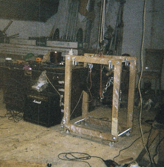
FRAME
The frame was built using oak flooring boards, I ripped in half and lamenated together creating a cross section of 40mmx60mm. I jointed the corners using lap joints as this gives triangulation to the structure and used strong polyurethane glue. The two oak sides were connected using threaded bar running between adjacent corners. This threaded bar was held held in place by washers and bolts.
Before I began working on this piece it was important that I had the skills required to produce it to a high quality piece in terms of the wood work and metal work required. I needed to build a wooden frame capable of carrying the 50kg+ of the engine as well as allowing accessibilty to work on the engine once hung. Producing the triggers meant using an angle grinder with great precision. It was important that I had an appropriate space to work in and so cleared the loft in the barn. I also had to consider the health and safety implications and take measures as required.
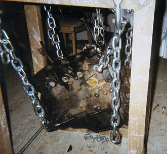
HANGING THE ENGINE
The engine was hoisted using a series of pulleys attached to a cross beam in the barn and the engine itself. This enabled me to position the engine at the correct height before attaching the chains to the shackles on the frame.This required a great deal of adjustment to get the engine sitting level as its weight was not evenly distributed and moving it was quite cumbersome.
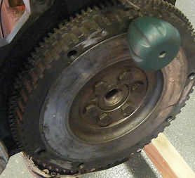
HAND CRANK
I chose to connect the handle to the flywheel as it would create the largest rotation thus minimising the amount of effort required to cycle through one rotation of the engine. I chose hand cranking as oppose to powering the engine by another motor for the following reasons. I could put more 'feel' into the way the engine was turning and would have more interaction this way. I also believe there is a certain theatrical appeal to hand cranking as it is reminiscent of how an automobile would originally have been started and wanted to put this across when performing. To get to the flywheel I had to remove the clutch and pressure plate and once removed, I bored out the holes which had connected these components to the flywheel. This took a long time to drill as the steel was very tough. With the holes bored to the correct size, the handle could be slotted into anyone of 6 and the engine could be turned easily.
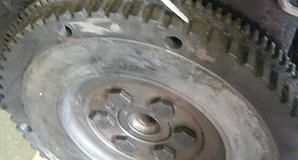
I removed the flywheel and used a g-cramp to keep it firmly in place over the side of my work bench. I used a power drill and 14mm metal bit to bore out the 6 existing 10mm holes. Drilling each hole took roughly 10 minutes as the drill needed to be kept at a low speed for the bit to be affective and for the drill to not over-heat. Once the holes were bored I bolted the flywheel back onto the crankshaft.
SPLITTING THE ENGINE
I wanted the workings of the engine to be visible and the pistons moving up and down in the cylinders were very important in this visualisation. With this in mind, I decided to raise the head using threaded bars in place of the bolts which normally attached the head tight to the block. I also did the same with the oil sump positioned beneath the block so the crankshaft could be seen rotating. I took the head to a metal works to get cut in half. This meant looking from top down, the two remaining cams could be seen rotating and two of the four pistons below were also visible. One of the aims of the project was to make the sounds I was producing visible and this helped greatly in doing so.

Lap Joint
The head is raised using threaded bars and nuts positioned (screwed to a certain height above the block). I needed to use the same timing belt to connect the block and head despite this change in height. I achieved this by removing the tensioner and water pump cog and introduced tension into the belt by increasing the distance between the block and head via the nuts on the threaded bar.