ENDA J O'REILLY DMI PORTFOLIO
TRIGGERS
I retrofited 8 triggers to the various components of the engine which produce varying rhythmic patterns or sounds of varying tonal quality. I attached each trigger with a contact microphone picking up the movement occurring and sending it via a 1/4" jack output. The triggers needed to be strong due to high forces involved in the movement of the parts and I did not want their ability to pick up sound to deteriorate over time, therefore they had to be durable. Finding the correct position and system to attach the triggers required a great deal of testing. I also wanted to make sure I could tune the triggers prior and during performances.
FLYWHEEL TRIGGER
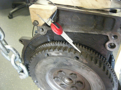
For the flywheel trigger I shaped a wooden wedge to slot a long strip of stainless steel into. It angled towards the flywheel at roughly 45degrees. I attached the wooden wedge via one of the existing threaded holes to the top left of the block. The stainless steel slip was held in place with Tech 7 silicon glue which allows an amount of flexibility whilst retaining a firm hold. The wedge rotates around the bolt meaning the strip is not always in contact and bounces as the flywheel is spinning. The contact microphone is attached along the metal strip to maximise the vibrations it can pick up. The sound produced is a course, broken, high paced pulse. I positioned this trigger to imitate the accelerator being opened on an engine and with pressure applied to the top, it produces a similar result with the sound it produces.
FAN BELT TRIGGER
For the fan belt trigger I first shaped a piece of wood and bore out its centre to allow it to be attached to a threaded hole positioned just above the fan belt drive. I then cut a narrow strip of stainless steel and gave it a 90degree bend to fit around the corner of the wooden section and used Tech 7 to attach it there. With the other end I put a slow bend through 90degrees to come into contact with the drive. I attached the contact microphone to the metal strip to maximise the vibrations picked up. The sound can be adjusted depending on the position of the strip when the bolt is tightened. This trigger produces a continual, white noise type sound.

PISTON TRIGGERS
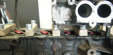
For the 4 piston triggers, I cut identical sections from the pressure plate as its shape meant I could attach each end level with the top of the block whilst the other end would scoop down into the cylinders. As the pistons move up and reach their highest point in the cylinders, they come into contact with these cut sections. I attached them level with the block using straight strips of wood and bolted them down using the threaded holes intended for attaching the head to the block. The contact microphones are attached flat to each of the sections. These triggers produce a note due to the metal section acting like struck tuning fork and the pitch can be adjusted by tightening the bolt or length of trigger in the cylinder. These triggers required a great deal of testing and trial and error due to the strong forces involved with the moving pistons. I am confident however that I have produced durable and effective triggers.


CAM TRIGGERS
I initially decided to attach 2 triggers to the rockers above the cam shaft as shown in the photo below but very close to the end of the project I decided to change this. I now have a trigger attached beside the cam cog which is driven by the timing belt. I was interested n the shape of the cam cog as the trigger attached horizontally produces a scratch followed by a tap pulse.

CHAIN TRIGGER
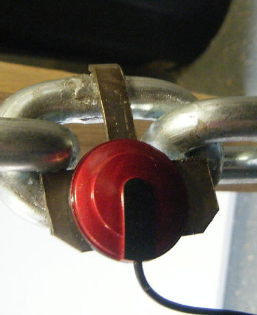
The chain trigger was intended to pick up sounds produced as the entire engine rocked within the frame. I cut a metal plate to attach securely to one of the links whilst allowing the chain to continue moving. This plate maximises surface area for vibrations to transfer to the contact microphone and also creates a more secure hold for the microphone. With reverb applied this sounds similar to swing doors in a empty factory.

The new trigger consists of a small strip of plastic pointed horizontally over the side of the head and in contact with the camshaft cog.
The choice to remove one of the triggers was also influenced by the scope for integration with other devices. I had an 8 1/4" jack snake I wanted to use and was also aware that it might be easier to use a desk which has 8 inputs as oppose to having 9 pulses and needed to use a 16 channel desk for this one additional trigger. This was a consideration in functionality driving the design.